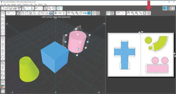
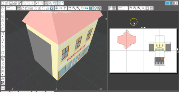
The Output Window is like a print preview page; whatever is displayed in the Output Window is what’s sent to the printer. The Output Window displays nets and projections, as they appear on the page, to be printed or cut with a Silhouette machine. A Shape Net is the 3D shape, unfolded and flattened.
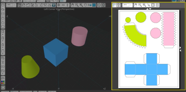
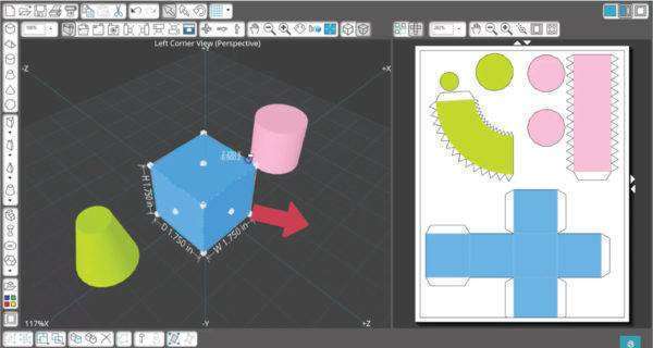
Nets as shown in the Output Window are directly related to the 3D shapes drawn in the Edit Window. Scaling a shape larger or smaller in the Edit Window causes the net to grow larger or smaller in the Output Window as well.
A net can be printed on cardstock, folded, and glued to make the original 3D shape. ModelMaker™ automatically adds glue tabs and score lines to the nets to help fold and adhere the sides together when assembling the physical model.
Nets are placed in an orderly layout in the Output Window, but you can rotate and move the shapes to make best use of the space on the page.
As you add shapes and resize them in the Edit Window, your Output Window may start to feel cluttered. Simply click the Auto-arrange Nets button to quickly organize the nets. If it needs to add extra pages, this is done automatically.
If you arrange the nets tighter and eliminate the need for extra pages, you can use the arrow buttons on the side and top to remove extra pages.

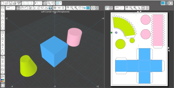
In addition to moving and rotating nets to fit better on the page, you can also break most nets into parts. You can do this by right-clicking on a net in the Output Window and choose Separate Net. This same choice is available when a net is selected and you go to the Nets menu.
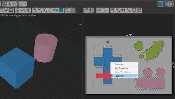
Extra glue tabs are automatically created, and you’ll see indicator dots appear so you know which side was separated and where it needs to be attached to its partner piece.
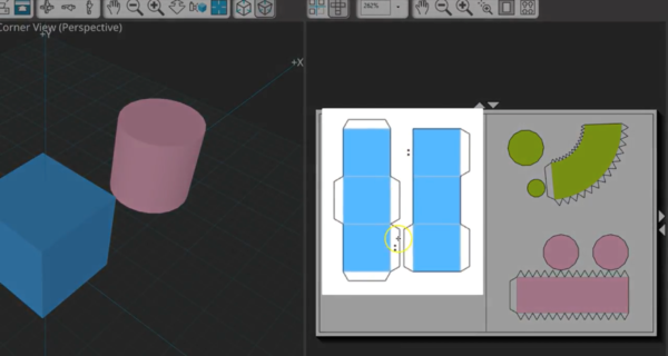
Now you can rearrange the separate parts on the page to fit objects tightly together and conserve material.
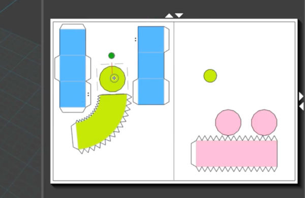
Another way to fit nets better on the page is with net permutations. Certain shapes like the cuboid, tetrahedron, hexahedron, and octahedron have a choice of net permutations. Right click on the net and choose Change Permutation to reveal permutation options, then choose the one that best fits your page.
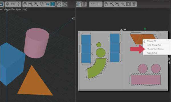
The final assembled shape will be the same no matter which permutation you choose.

That’s how to work with the Net View in the Output Window. There’s also a Projection View in the Output Window. We will change documents so you can see a better illustration. This view shows an orthographic projection, which is simply a way of representing a 3-dimensional object on a piece of paper where several 2-dimensional views of the object are used instead of a single view. An orthographic projection includes six views of an object, including front, back, right side, left side, top, and bottom. A standard orthographic projection normally includes three of these views, which is considered to have enough information to make a 3-dimensional object. ModelMaker™ defaults to the third angle projection showing front, top, and side.
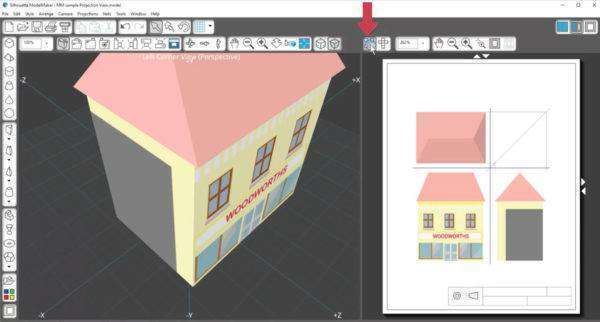
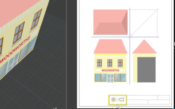
The symbol showing this projection can be seen at the bottom of the drawing.
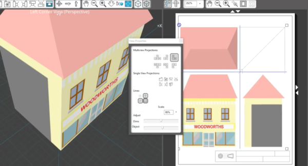
If you want, you can change the views by right-clicking on the Output Window drawing and choose Properties. In this View Properties panel, the top row shows your options with the third-angle projection, the second row shows your options with the first-angle projection, and then you can also show a variety of single-view projections. You can toggle other options on and off here like construction lines, divider lines, corner construction lines, and the name box. Adjust the scale of dimensions or the full drawing. Even if your model is quite large, you can reduce the scale to view the full drawing in the Output Window.
If you’re not into the engineering or architectural side of ModelMaker™, stick with the Nets view to print or cut your models.
That’s the Output Window. Be sure to check out our tutorials on ModelMaker™ printing and cutting to find out how to get your models from the Output Window to finished printouts and cutouts that are ready to assemble.